432MHz GS35b Cavity
This chapter descibes the build of a my 432MHz cavity. It uses a GS31b tube at this moment (January 2008), but change to a GS35b is due to happen in short time. Because the tubelife for the GS31b is twice the tubelife of the GS35b, combined with the low drive power I get from the TS811e transceiver, I decided to first use the cavity at only 450W RF output. The 20W drive power would never be enough to drive a GS35b to it's maximum power. I am now in the process of constructing a brick amplifier from a 250W BLF258 transistor. This should deliver enough drive to be able to get the GS35b to it's dissipation limits...
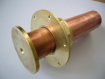
Cavity housing:
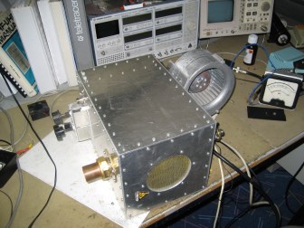
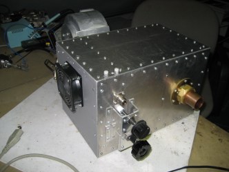
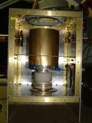 On the picture shown to the left, the final result of the cavity is shown. It is a quarter-wave resonator made from a brass tube that has an inner diameter closely the same as the tube anode diameter. This choice made the build of the resonator quite easy because only 6 cuts had to be made by a saw. After sliding the anode into the brass resonator a simple hose-clamp holds the assembly together.
Like the RX1AS 144MHz cavity design, the plate and load circuit is made from disc material that can be adjused to and from the resonator the tune the assembly.
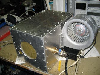
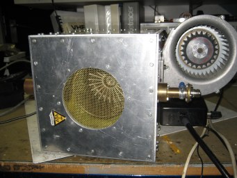
A blower inlet is situated just above the aluminum plate on which the grid ring is mounted. To ensure air is flowing through the radiator of the tube, an air barrier is placed that seals the resonator to the inner of the cavity. In this way the air from the blower is forced to flow through the anode cooler of the tube, leaving the cavity at the top through the brass mesh.
As can be seen from the picture, the sidewalls of the cavity are screwed together by using brass square profile into which M3 threads are cut. This turned out to be very labour intensive, and therefore the construction of the 144MHz cavity is using M3 press fit nuts for this. Take a look here for the details on this.
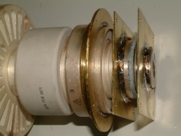
Tube socket:
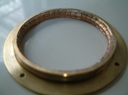
The tube socket is home made. It is made from a piece of 2mm brass plate that is cut and
 filed to round shape. The grid contact ring is soldered on top of this brass plate and fingerstock material is soldered into the ring. It was quite hard to find exactly a piece of brass tuning that together with some spring force of the fingerstock material had the right inner diameter. At the time of the build I had no lathe available to machine a ring from a little too less inner diamter material. Therefore I deciced to a piece of brass tubing that had the next larger inner diameter compared to was needed. I made a ring of 7mm height and cut a piece of material from it. I then pressed the ring while checking the inner-diameter with fingerstock on right spring force. After two or three more material cuts (every time 1 or 2 mm...) the outer diamter could be measured. This was now cut from the 2mm brass plate that is meant to be screwed on top of the aluminum plate that holds the tube socket in the cavity. The brass ring is now (while pressed togehter) soldered into the opening. This method is chosen to have more soldering area and give more strenght. Also because of the ring now pressed into the opening of the brass plate material, the soldering of fingerstock material into the grid ring is made very easy. The ring cannot widen itself any more because of the tight fitting into the plate. filed to round shape. The grid contact ring is soldered on top of this brass plate and fingerstock material is soldered into the ring. It was quite hard to find exactly a piece of brass tuning that together with some spring force of the fingerstock material had the right inner diameter. At the time of the build I had no lathe available to machine a ring from a little too less inner diamter material. Therefore I deciced to a piece of brass tubing that had the next larger inner diameter compared to was needed. I made a ring of 7mm height and cut a piece of material from it. I then pressed the ring while checking the inner-diameter with fingerstock on right spring force. After two or three more material cuts (every time 1 or 2 mm...) the outer diamter could be measured. This was now cut from the 2mm brass plate that is meant to be screwed on top of the aluminum plate that holds the tube socket in the cavity. The brass ring is now (while pressed togehter) soldered into the opening. This method is chosen to have more soldering area and give more strenght. Also because of the ring now pressed into the opening of the brass plate material, the soldering of fingerstock material into the grid ring is made very easy. The ring cannot widen itself any more because of the tight fitting into the plate.Of coarse everything would be much easier in case someone can machine such a assembly on a lathe, but I want to share my method here and show that also by using a iron-blade saw, a file and some patience, the result is also perfect...
The rest of the tube socket is not very difficult to make. Two pieces of 1mm brass plate are cut into a square shape. Into the two plates holes are made in such diameter that together with the fingerstock material good contact is achieved to the tube.
Important: Drill prior to insertion of the fingerstock material 4 holes through the total assembly of the tube socket. These 4 holes must align insuch a way that 4 nylon bolts can be used to create the correct distances.
Below are three detailed pictures showing how it should look like:
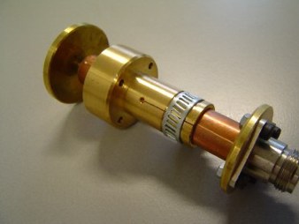
 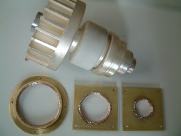  GS35b tube socket for the 432MHz cavity
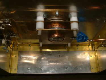
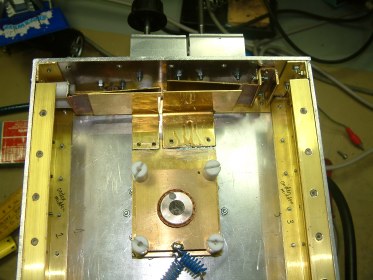 Improved tuning system at input of 432MHz cavity
  Output and tuning discs, made by PE1NFE Frank (thanks)
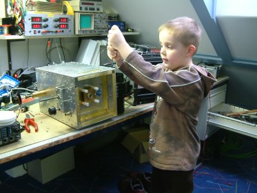 My son Robin, here only 5 years of age, helped during assembly...
Here some more pictures of the completed cavity were you can also see the blower:
    The cavity for 432MHz is connected to a homemade power-supply like is used also for the GS35b amplifier for 144MHz. The two amplifier are aperfect match as can be seen in the below picture:
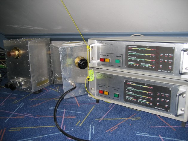 |