Amateur Television (A.T.V.)
70cm AM-A.T.V.
I started ATV years ago and was started this part of our hobby building an AM-ATV transmitter designed by DC6MR. This was a very big PCB that included all parts needed to be QRV on 434.250MHz with amplitude modulated television tranmissions. It included the video-amplifier, video-modulator, large discrete build filter for lower sideband, audio-amplifier, video/audio combiner and small output-amplifier. When correct adjuted, this PCB was able to deliver about 10mW output.
As time passed by, AM-ATV techniques improved and another German HAM designed a more sophisticated design. This design realy became famous and it was copied a lot amounf Dutch Radio-Amateurs. The design became famous under the name 'DJ4LB-ATV transmitter'.
What was especially nice about the DJ4LB-design was the modular approach this German HAM did. All building blocks were build in seperate tin-boxes and could all be tested individually. I used this design a lot and again learned a lot about electronics in the years that pasted. It was a lot of fun not only using the homebuild electronics, but the building itself also gave me a lot of joy.
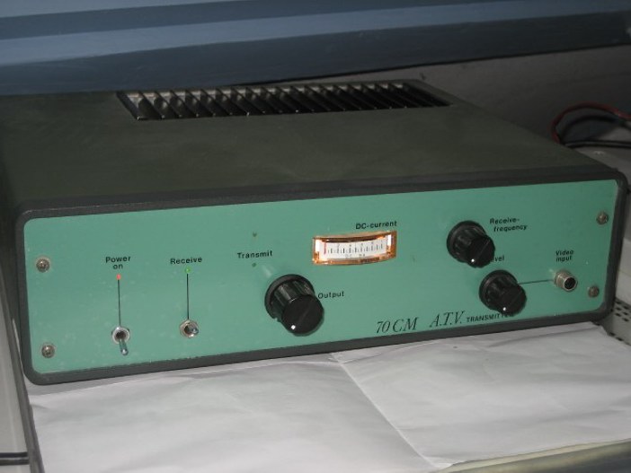
A few years later, I got attrackted by a special nice and small design that uses a dedicated video-modulator chip made by Philips. This chip (TDA5664) was used by a firm called RSE-electronics to combine it into a complete kit. The kit holds all functions in one small tinned box and gave very nice quality picture and sound.
 To the left here, you see the tinned box containing all neccessary items to complete a AM-ATV transmitter. The kit delivers only a small RF-output and needs amplification to be of any use.
Inside the box, I added at the output right in between the wire to the output connector a small amplification-stage.
This gives the kit just enough output to be able to connect a Power-Module.
The power-module is a Mitshubishi module that is also build into a tinned box. The power-module is capable of delivering 35W (in class AB1 SSB), so I thought this should be best choise for the ATV-transmitter that needs very linear way of amplification of the RF-signal. If this is not done with care, the picture that is transmitted is distorted and sometimes even not delivers a picture that can be synchronised by the TV it is wached on.
Below here you can see a detail of the Misthubishi power-module that is build into the 70cm ATV transmitter:
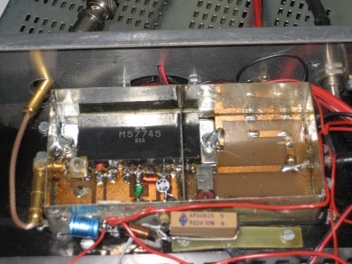 The power-module (M57745) is build in a tinned box. Inside this tinned box is filtering made for the second and third harmonics. This filtering is etched on the same PCB were the pins to the M57745 module is are soldered. The filter consist of two stubs (series-resonance) to 2x434MHz and 3x434MHz.
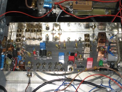
The 70cm ATV transmitter using the RSE-electronics kit has a build-in power-module.
At the fontpanel are controls for output power, video-level, but also a third control that can set the receiver-frequency.
The build-in receiver makes the transmitter not only capable of transmit ATV-signals, but also can receive signals from other amateurs. The receiver is part of an old regular TV:
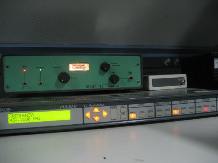
 My current 70cm AM-ATV transmitter is a BARCO cable-TV modulator, capable of transmitting in a range of VHF to UHF. Luckely there is no limitation and 434.250MHz is also able to select. This BARCO-modulator only deliverers a few mW, and a subseeding amplifier is needed.
The intermediate stage that is used to amplify the tiny output (2mW or so) of this BARCO-modulator is a Mitsubishi M57745 power-module. The type I use is able to generate up to 35 watts in SSB. It is still build inside the ATV-transmitter that I have build years ago. The picture below is showing this project.
Because the BARCO-modulator is a commercial product, the quality of the picture is much better compared to the RSE-design modulator in the original ATV-transmitter. I have made the input to Mitshubishi power-module accessable at the rear of the housing, making it easy to use the original RSE-design to operate again.
The current setup with the BARCO-modulator and the Mitsubishi power-module inside the 'old' ATV-transmitter is shown below:
 To enlarge the output from the Mitsubishi power-module even further, I now use one of the Motorola TTE1482e SSPA modules as descibed in the 432MHz section. This solid-state power-amplifier is capable of 200W and can be used from 420MHz - 468MHz without tuning. This amplifier is a 3-stage transistor PA, running at 12-14V consuming a whopping 30A at full power...
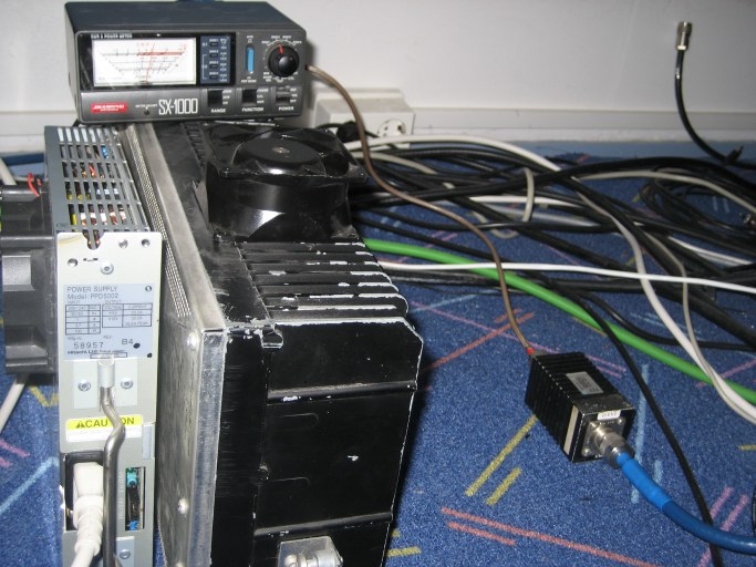 In the picture above you can see the setup for 70cm ATV running at some 125W output. The blowers at the side of the switched-mode powersupply as well as the blower on top of the huge heatsink of the final-stage enable me to be 'on-air' for 24 hours, 7 days a week. Not that this happens, but it is more to be on the safe side.
This Motorola amplifiers uses 3 stages. The final stage consists of two power-transistors in parallel. Originally the amplifiers were used in class-C, so I had to modify them to have class_AB1. In the 70cm pages this modification is shown, but to be complete I show the interior here once again:
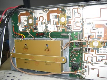 To run the TTE1482e in SSB, I needed to add four BIAS-circuits. These enable the four transistors to be set to class-A.
In the picture the BIAS-unit is shown, mounted in the space were the circulator-board is removed. The circulator was limiting the frequency range were the amplifiers could be used. After removing it, the amplifiers turned out to be usable from 430-470MHz.
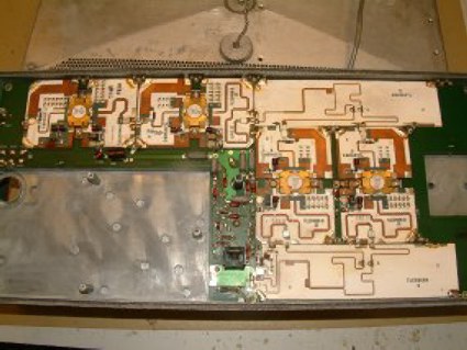 Here you can see the interior of the Motorola TTE1482e amplifier that is in use for 70cm ATV.
In the upper left corner is the input-stage, to the right the intermediate stage and at the righthand side the double output-stage. The output-stage is internally coupled by so-called wilkinson dividers.
The small black block is a diagnostics connector. At this point I can monitor all collector-currents in the four transistors as well as relative output-power from the build-in forward-power sensor.
|