Amateur Television (A.T.V.)
23cm FM-ATV
My 23cm ATV-transmitter is build in the same housing-style compared to the 70cm ATV transmitter. The 23cm transmitter however is capable of changing operating frequency over 1250MHz to 1285MHz by using a PLL-circuit. The transmit-frequency can be changed by UP/DOWN buttons on the frontpanel. Inside the housing a preset-frequency can be set by means of DIP-switches. At power-ON, this preset frequency is selected. Audio-frequency is also selectable from the inside and fixed to 6MHz.
Here is a picture of the 23cm ATV-transmitter:
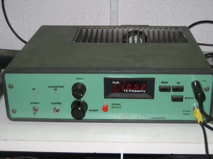 Like the 70cm version, also this transmitter has a Mitsubishi power-module build in. At the frontpanel the output-power also can be changed. Maximum output-power for the 23cm version is 15 watts. The small blower at the back is temperature-controlled and when needed is changes speed to keep the heatsink at moderate temperature. This is the same in the 70cm version.
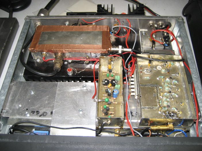
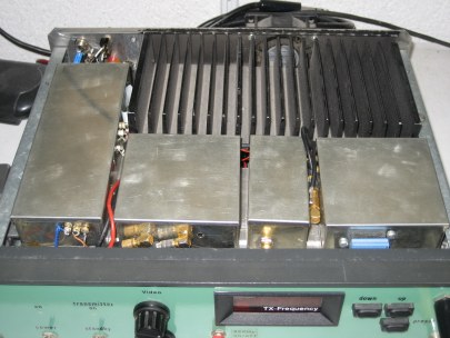 The 23cm ATV-transmitter is build in a modular way. Each individual part is build in a small tinned box. This build-up is shown in the picture here. Also the heatsink for cooling the power-module is clearly visible, with the small blower at the rear.
In the below pictures you can look inside the individual tinned boxes that builds the 23cm ATV transmitter:
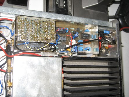 This is the module that generate the audio-carrier. It uses a PLL-circuit that gives possibilities to set the audio-carrier frequency at any frequency between 5MHz and 9MHz. The small bread-board add-on is a 22kHz oscillator that was used in the past to control a specific function in our local ATV-repeater PI6ZOD. This function is no longer active in the repeater anymore.
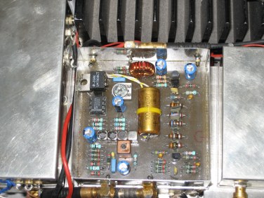 Here is the baseband-module board shown. Inputs are video as well as the audio-carrier. Both signals are combined in the toroid coil.
Output from this baseband-module is the baseband-signal that is used to modulate the oscillator. This oscillator is a voltage-controlled oscillator and part of a PLL-circuit. The VCO has two ways to control its output frequency: one is the DC-control for its output frequency, the second input is the baseband-signal from this baseband module.
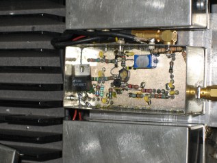 This is the VCO (Voltage Controlled Oscillator) that is used to generate the 23cm ATV signal. It generated 10mW. The oscillator is still build from discrete components, were nowadays ready build VCO's are more and more pratice.
The ouput-frequency is locked by means of a PLL-circuit. A small amount of RF from this oscillator is fed back into a divider circuit and compared to a crystal-oscillator. Any deviation from the desired frequency is compensated by a offset on the DC-control voltage.
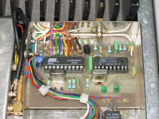 Here the PLL-module is shown. The small RF-signal that is derived from the VCO-module is divided in a special chip and compared to the wanted frequency.
An ATMEL controller is used to generate the serial clock and data to the PLL-circuit. Input for the wanted frequency is the UP/DOWN buttons at the frontpanel of the transmitter, but also some DIP-switches inside. These DIP-switches are used to set a default output-frequency at power-up. This default frequency can also easily be activated by pushing the 'Preset' at the frontpanel.
To complete the 2cm ATV transmitter an amplifier is build at the oppsite side of all the tinned boxes. This amplifier is a part of the transmit-mixer of an old 23cm transverter and a Mitshubishi power-module that can deliver 20W. The setup for the amplifier is shown below:
 (The small breadbord PCB contains a 2-frequency equalizer circuit that boosts bass and trebble for the audio. )
|