13cm_transverter
Transverter:
My 2320MHz SSB station consists of a transverter from VHF to 2320MHz. The IF is 146MHz (not 144MHz) and is chosen not to be exactly on 144MHz because this equipment is meant also to be used during fieldday activities were in the close vacinity large 144MHz signals are expected. The original design for the transverter needed only be adapted for the crystal oscillator. All tuning could be done 2MHz higher than original without any problems.
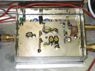
This transverter is build ina modular way because that allowes measurements on indivudual parts. The moules are all build into tinned boxes and have RF-connectors that connects intermediate cables to the other boxes:
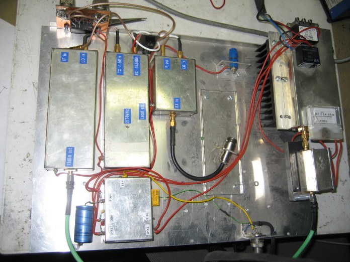 The IF-Input to the transverter is found in the above picture in the left upper corner. This shows two PL259 chassisparts. One PL259 is connected to the IF-tranceiver, the other PL259 chassispart can be connected to another transverter. This is possible because there is a small relais mounted that connects the PL259 in case this transverter is not switched ON. As soon the transverter is switched-ON, the IF-tranceiver is connected to the TX/RX relay of the transverter that is the black relasy in the picture were the white coax-cables run to.
The transverter is build from the next items:
Local Oscillator:
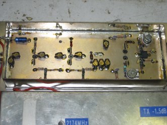
The local oscillator in this transverter uses a temperature controlled crystal oscillator (TCXO) to ensure the correct and stable output frequency. The oscillator is from its origin a normal crystal oscillator, but by adding an power-transistor that is mechanically coupled to the crystal, the circuit is converted into an TCXO.
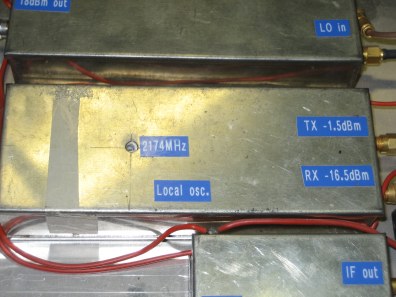 The output of the crystal oscillator is multiplied several times to end up at 2174MHz.
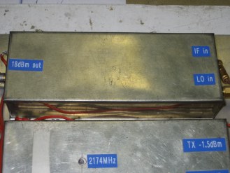
As can be seen from the picture, the local oscillator gives two outputs, one is to the RX-mixer (-16.5dBm), the other to the TX-mixer (-1.5dBm)
 The coil in the crystal oscillator circuit can be adjusted from the outsided when the lid is on the tinned box. The isolation material that gives better temperature behavior and is to improve the stability over temperature.
Receive mixer:
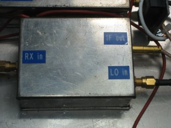
The receive mixer consists of a single-stage MGF1302 GaAs-Fet stage to were the antenne-input is connected and a second MGF1302 as an active mixer. At the gate of this second FETis a coupling-loop that is connected to the -16.5dBm output of the local-oscillator. At the drain of the FET is the mixed product available (2320.2MHz - 2174MHz = 146.2MHz). The output to the IF-tranceiver is filtered and adjustable by the Neosid core.
  Transmit mixer:
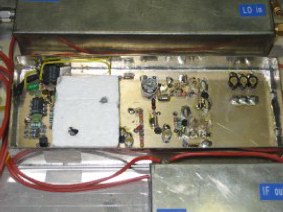
The transmit mixer is needed to mix the TX signal from the IF-tranceiver up to 2320MHz. Therefore the larger signal from the local oscillator box is mixed together with the 146.2MHz signal which ends up in 2174MHz + 146.2MHz = 2320.2MHz which is the 13cm SSB frequency we use in Europe.
The TX-mixer in this transverter uses 2 stages of amplification towards the output connector. The maximum output at 2320MHz is measured to be +18dBm (almost 60mW).
Below you see the tinned box for the transmit mixer, to the right the opened box. The mixer itself is an active mixer build from two UHF-transistors BFR96. Last stage in the transverter is a BFQ31T.
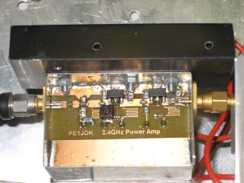
  Driver-stage (0.8W)
To give this transverter the needed output power, a driver stage is build to amplify the 18dBm signal from the transmit mixer to about 1W. The driver is build according the PE1JOK design that is used a lot amongst ATV-Amateurs at 13cm. The driver uses normally 3 stages, but because I already had +18dBm, I reduced to two stages, a CLY5 and a CLY10:
In the pictures below you see this driver stage. At the right the inside of the tinned box. The three stage design is reduced to 2 stages by bypassing the first stage by a SMD capacitor. The CLY5 and CLY10 generate some heat and because of that a small heatsink is mounted to the tinned box. The driver is connected to the 10W final stage by simply using SMA-SMA connectors. This also reduses losses in the path towards the final stage.
  The bottom-side of the driver-PCB contains electronics for the power-suppy of the CLY5 and CLY10.
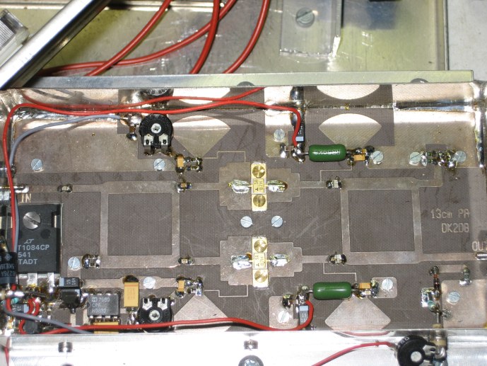
Final-stage (10W)
The final stage of the 13cm transverter consists of a 10W amplifier that is bought as kit from DK2DB (purchached from Eisch Kafka). It used 2 FET's MGF0905 and is type PA13-10:
 The 10W from the transverter final output is fed through 35meter H2000flex cable to the 40W BLF2047 final stage mounted at the rearside of the 1.6mtr. mesh dish. The 1W that arrives there is not quite enough to achive the 60W RF output that is maximal achievable, therefore another final stage is planned that incorporates two stages and can give 80W RF at 18dB Gain. This amplifier is a piece of the well known Spectrian ampifiers sold in large numbers among HAM's for 13cm.
(Januari 2010):
Currently these plans for the 80W Spectrian is put aside as I got hold of a bigger PA containing 4 MRF21085 transistors in the final stage driven by another MRF21085. This project as well as the Spectrian amplifier can be looked by clicking the other links at the left.
Sequencer:
To control all stages in the transverter a sequencer is used. This unit makes sure that for instance the preamp mounted at the antenna is switched down before the transmit power is generated.
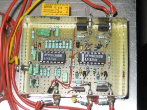 The sequencer is a popular design that works great. It was originally published in UKW-berichte, a German magazine wellknown amongst UHF/SHF Radio-Amateurs. The principle is a slow rising and faling DC voltage that is monitored by 4 camparators. As soon as a comparator-level is reached, its output changes and activates or de-activates a output transistor. This can be used to control a relay (like the yellow one in the picture).
|