YU7EF 0210LT (ultra-lightweight)
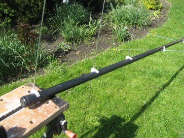 For contest, MS and tropo DX I am currently building a couple of new yagi's. They are the 10el. 0210LT concept made by YU7EF. I choose the boom to be made from fibre-glass, like G4DHF also did. By doing this, 4 yagi's can be arranged vertically in my Versatower. On the above picture first work is done by assembling the elements to the boom. The correct alignment is not done yet, only right clamps are selected from different diameters to fit best on the variation in diameter diameter of the boom (large diameter at the end, small at front).
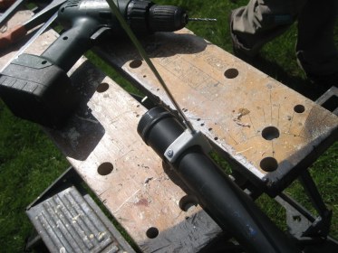 Here you can see the fixation method of the clamps to the boom. Simple method, low costs...
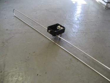
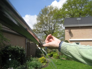 A completed yagi is very light weight! Here I hold a yagi balanced on one finger. The yagi is just over 5 meters in length and has 10 elements.
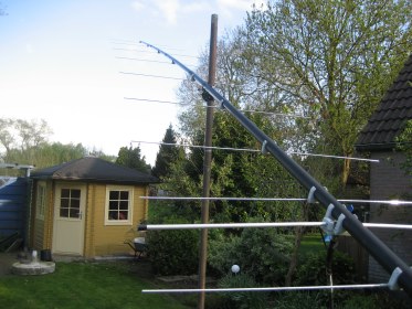 In the above picture the 0210LT yagi is ready for VSWR testing and alignment. The driven element is at this moment a coaxial dipole, like described also in the chapter for the 2SA13 antenna with coaxial dipole. Currently it is not sure whether this is the right and final solution for the driven element.
Update (16th of August 2008):
I decided to change the dipole to a folded dipole in conjunction to a well known half-wave Balun. This because after some more study on the coax-dipole I was not sure whether this can be used without a 1:1 Balun as described by the author. To take no risks I changed the configuration and here are some pictures and results:
The dipole is made from 6x4mm Aluminum tubing, and made on a fixture. This fixture is very handy to use, especially when having to make more than only one dipole. As I plan to make a vertical stack of these yagi's I made a simple fixture to bend the aluminum tube. There is no need to take further measures, the 6x4mm tube is not deformed in the curves at the dipole ends. Some fill it with sand and make the tube hot by flame, I simply tested some scrap material and found these measures not needed for my material.
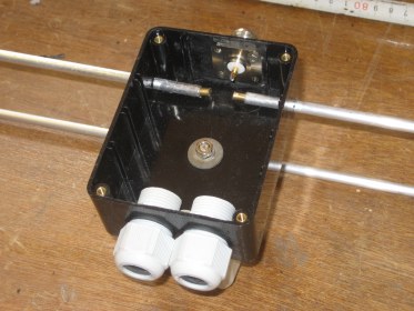 To the left you see the prepared plastic box that holds the N-chassis part for the feeder, two inlets for the Balun and the inlets for the dipole.
To connect the Balun and the N-chassis part to the dipole I hammered brass pieces into the aluminum dipole. This is giving a very tight fit, and when later protected against weather influences (epoxy glue is poured into the box) no degradation is expected.
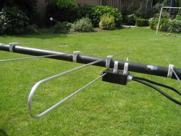
 This is an overall picture of the dipole. You can recognize the large clamps that hold the box onto the fishing-rod like the other elements are mounted. The dipole itself is fixated with a additional plastic clamp to prevent variation in the distance of the dipole (when f.i. birds sit on it...)
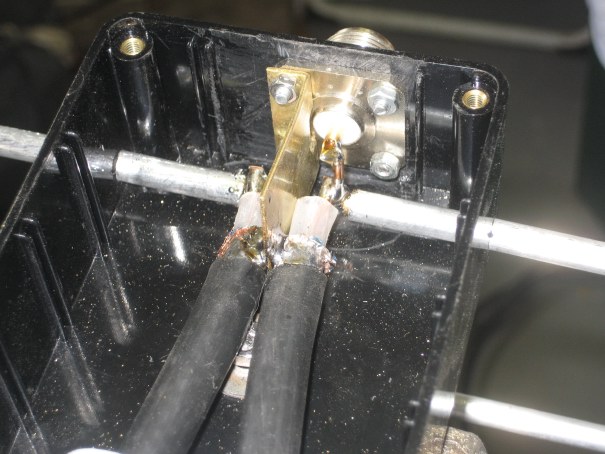
To connect the N-chassis part and the Balun to the dipole, there are hammered small pieces of brass into the ends of the dipole. This is already a proven method in the 2SA13 yagi that is operational already one year now. In that yagi even no plastic box is used and only epoxy-glue is used to protect the transition from brass to aluminum from corrosion. If you take a carefull look you can see the solution I did to connect the ground of the N-chassis to the outer conductors of the Balun coax (Aircom-plus). It is made from a small piece of brass material that is made in a 90 degrees angle and screwed to the inner of the N-chassis part. It runs at distance between the two ends of the dipole and the inner conductors of the Balun to the braid of the Aircom-plus Balun. There it is soldered together.
By using this method, the Balun comes at the backside of the box, pointing towards the rear of the yagi. The feeder comes in at the front of the box, being able to fix it along the boom towards the mounting pipe of the tower.
 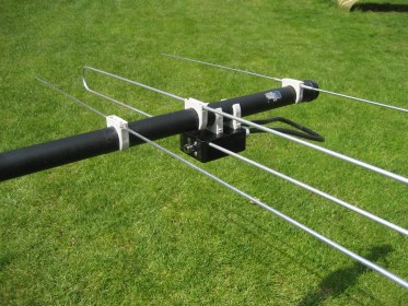  In the two above shown pictures, the whole dipole is mounted onto the boom. Here the three clamps that hold the dipole in place can also be clearly seen. The dipole as well as the first director are not yet mounted to the boom at there right locations. This is done afterwards the measurements shown good VSWR.
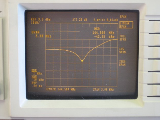
After some fiddling around with the distance to the first director as well as the location of the dipole and the 1st director, very good return loss is achieved. Because the designer of this antenna (Pop, YU7EF) did all he could to achieve best surpression of sidelobs and rearlobs, he needed to shift the resonance frequency slight away from the SSB-section of the 144MHz band to 144.500Mhz. During our experiments to achive best VSWR we take good notice on that and got is right finally. The below picture is taken from a Spectrum-Analyser with tracking function that, in combination to a VSWR-bridge, is of great value in these kind of work:
 |