Phase-lines EME
To connect the 4-bay yagi to the splitter/combiner, I use very cheap CATV COAX-3. The only 'problem' is the impedance of 75Ohm. Many say this is very little difference to the 50Ohm but I am afraid of strange impedance transformations in the 1/2 wave splitter.
In my case technique gives a hand and I used a Spectrum-Analyser with tracking options to cut the phasing lines to exactl multiples of 1/2 lambda. The overall length that I needed was about 4 meters to come from the dipole to the splitter. It is known that a piece of 1/2 lambda coax is transparant for impedances, which means that the 50Ohm of one yagi is also 50Ohm at the other end of a 75Ohm typical impedance coax cable, when cut to exact multiples of 1/2 lambda.
As the used frequency is limited to only 144.000MHz to 144.200MHz, the choise was simple. It is in theory given a cheap and very low loss phasing harness, mind the cable is 22mm diameter. This is even bigger and lower loss compared to the Ecoflex-15 alternative!
 The COAX-3 did not come with the connectors, and if it were available, how to connect to the N-style connectors on the splitter? I choose again the cheap way and solder N-connectors direct to the COAX-3.
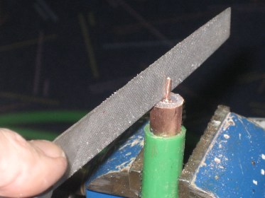
To do this, you must first reduce the inner conductor of the COAX-3 to such size that is fits to the 50Ohm centre pin of a standard N-connector. Is this not a jump in impedance one could ask? No it is not because the length in between two N-connectors is matched to the 1/2 wave multiples and is not creating unwanted impedance jumps. Later you will see the result.
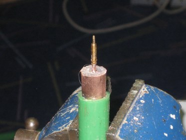 Here the centre pin is mounted. There is enough material for the inner conductor of the COAX-3 left to give a stable result.
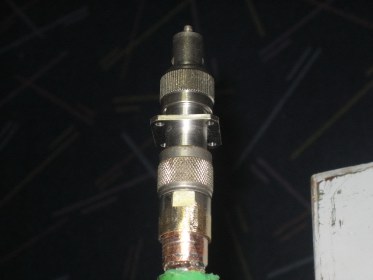
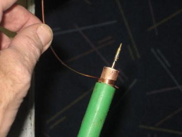 Now the outer conductor of the COAX-3 must be increased to fit the inner diameter of the N-connector were normally the adapter is screwed in (RG213/H2000flex-type). This is done by winding copper wire around the outer coax conductor. The result is a too large diameter outer-conductor. No problem that is needed. Now the copper-wire is soldered completely to the screen of the COAX-3. After that, the copper-wire is carefully reduced by filing to the diameter of the N-connector. Keep trying and do not reduce too much. After a nice tight fit is reached, the N-connector can be soldered to the pre-tinned copper-wire. The windings of the copper-wire reach approximately 8-10mm into the N-connector part. It is adviced to use a piece of sandpaper to clean the N-connector, this gives better soldering results. Now the outer conductor of the COAX-3 must be increased to fit the inner diameter of the N-connector were normally the adapter is screwed in (RG213/H2000flex-type). This is done by winding copper wire around the outer coax conductor. The result is a too large diameter outer-conductor. No problem that is needed. Now the copper-wire is soldered completely to the screen of the COAX-3. After that, the copper-wire is carefully reduced by filing to the diameter of the N-connector. Keep trying and do not reduce too much. After a nice tight fit is reached, the N-connector can be soldered to the pre-tinned copper-wire. The windings of the copper-wire reach approximately 8-10mm into the N-connector part. It is adviced to use a piece of sandpaper to clean the N-connector, this gives better soldering results.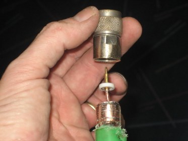 Here one of the 8 N-connectors in my phasing harness is mounted. You can see the reduced tinned copper-wire around the outer conductor of the COAX-3 clearly. I also keep the teflon washer in place to center the inner pin.
 One end of the phasing line is not soldered immediately! The copper-wire to enlarge the outer coax diameter is only applied in a very late stage, only when you left to cut a few milimeters to reach the multiple of a 1/2 lambda. Until this stage the centre pin as well as the outer of the coax is only contacting the N-connector. In the measuring setup, in this case the N-connector in its turn is connected to a Female-to-Female were a dummyload is mounted to. One end of the phasing line is not soldered immediately! The copper-wire to enlarge the outer coax diameter is only applied in a very late stage, only when you left to cut a few milimeters to reach the multiple of a 1/2 lambda. Until this stage the centre pin as well as the outer of the coax is only contacting the N-connector. In the measuring setup, in this case the N-connector in its turn is connected to a Female-to-Female were a dummyload is mounted to.The final milimeters are only cut from the inner conductor of the COAX-3. This gives just the amount of length change in the phasing-line that is needed to bring the multiple of 1/2 lambda to the desired frequency.
One tip for soldering the N-connector to the Coax cable: Carefully clean the surface of the N-connector, also the inside. In the above picture the brass of the N-connector is visible, this is good solderable. Use a paint remover heatgun to heat up the total assembly. As soon as the temperature is high enough, solder the outer conductor into the N-connecter by means of a 100W soldering iron and big diameter soldering tin. The heat will melt a bit of the green outer of the coax, but that is not harmfull. Once the temperature is low again, carefully cover the N-connector and the exposed copper of the coax with PVC-tape.
Furthermore it is known from these green colored kind of cable that they do not very good resist UV-radiation. Therefore I have covered the complete coax used in the phasing harness in black PVC-tape. It helps for durability and also after this time-consuming job, it looks you have 50Ohm coax with big diamter and low loss used. The last two are valid, it is big diamter and it is low loss for sure. I could not measure any attenuation as my setup was 0.1dB accuracy.
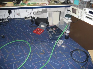 Measurement setup. Spectrum-Analyser with tracking option, VSWR-bridge connected to that and of coarse the phasing line under construction.
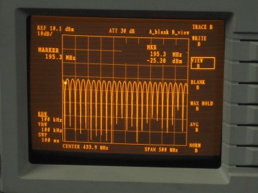 When connecting this piece of 75Ohm coax cable that is terminated by a 50Ohm load to a tracking generator and Spectrum-Analyser, this is the result on the screen. Bare in mind, a VSWR bridge is used to measure to which frequency the total load (Cable terminated by 50Ohm gives good match)
When zoomed into the desired frequency, the below picture can be seen on the analyser screen:
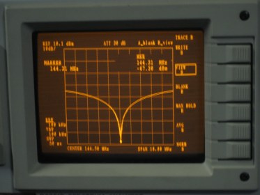 When cutting of the COAX-3 is done (last steps only 1 millimetre at a time), this is a result that can be achieved. The dummyload at the end of the 75Ohm cable is 1:1 measured at the VSWR-bridge. No strange impedances at this 144,310MHz. The span of the analyser was 10MHz, which means that also at 144.000MHz the match is still >50dB.
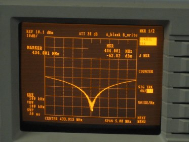 As we all know that 432MHz is a nice multiple of 144MHz, it's nice to check how much return loss is to expect from this trick for 70cm phasing lines made from 75Ohm CATV cable.
In the picture here you can see that the same good result is achieved for 432MHz frequency. Altough not exactly at 432.200, but that is due to the fact that during this experiment a 144MHz phasing line was used and no effort was put into matching at 432.200MHz.
|