PA3BIY Preamp (rebuild)
Due to busy QRL I cannot take new orders at this moment (27 April 2011), please check here later this year for changes in this situation. Running orders will be finished though.
Currently the PA3BIY rebuild preamps are in use at:
Background:
After using the DJ9BV PreAmp (see other page in this web-site) for quite some time, it was time for a
higher performing PreAmp. Because some other HAM's in my vicinity also were starting this project, or even were already finished with good result, I decided to go for the PA3BIY design.
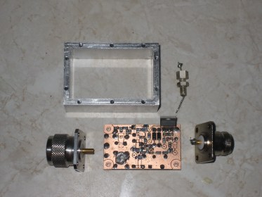
Mechanical considerations
Together with my QRL-collegue and HAM-enthusiast Frank (PE1NFE), we decided to do a re-design on the original PA3BIY PCB (see link at the left). The original design was too big according to our ideas because we targeted the PCB to be mounted in a piece of 30mm long, 60x40mm aluminum profile. This profile is selected because of the lack of milling machines in our hobbyrooms and QRL. Were we see other HAM's capable of producing nice aluminum boxes to the exact dimensions needed, the here presented solution can be completed by everyone. The only mechanical work involved is the engineering of some M2.5 or M3 threads around the edges of the aluminum profile to mount the top and bottom. Also the input and output can be fixated in a mechanical stable way because of the wall-thickness of 5 mm. This ensures a stable box, that does not show the variation in NF-factor found in the tinned box housing of the DJ9BV PreAmp.
Building the PCBA
The original PCBA (Printed Circuit Board Assembly) was too large in dimensions to fit in the 60x40mm aluminum profile. Because of this, the schematics was re-entered in a PCB-CAD system called Eagle from which a new PCB was generated. The Eagle CAD software gives the possibility to generate GERBER-files that can be transferred into LMD-files. These files are used to control a LPKF-PCB milling machine which is used to mill the PreAmp from double sided FR4 material.
  Results
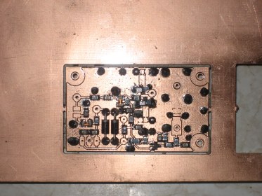
After completing the mechanics, of which the result is shown in the below picture, the re-designed PA3BIY PreAmp PCB could be measured on performance. It's Forward_gain is determined on a vector-network analyzer, a sophisticated piece of equipment also capable of measuring the Input_return_loss factor, Output_return_loss and Reverse_isolation.
 In the table below, the 5 most important measuring results are shown. The NF-factor is measured during a HAM-meeting in January 2008 in the Netherlands in Westendorp, also known amongst VHF/UHF/SHF-amateurs as the annual Heelweg-meeting.
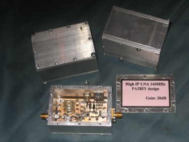
Our HAM-friend Eric PE1RLF, delivered another 2 boxes to complete two additional PreAmps. One of these PreAmp's will be used in future by Roel, PA1LA. Eric did a fine job in machining the boxes with great precision. He uses 4mm aluminium material for the top and bottom, were my PreAmp only uses 1.5mm thick material. This will not influence the performance.
Meanwhile there have been quite a large number of professional PCB's manufactured. These PCB's have the same layout compared to the proto-type that is shown in the above picture inside the aluminum box.
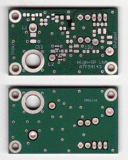 This is the result of the professional produced PCB. It has two layers, connected by means of through hole VIA's. These ensure good electrical contact from top to bottom and safe a lot of labor not needed to make manual connections from top to bottom anymore.
I have now finished one unit on this professional PCB and after some help of our HAM-friend Graham F5VHX, I managed to get the PreAmp performing very good and stable. The gain turned out to be even higher compared to the prototype and was measured at 24dB. No signs of oscillations were noticed in the RF-spectrum from 0 - 26GHz. Even as the input connector was left open, no spurious signals on the output were noticeable.
Measurements on NF-factor will be performed as soon as there is an opportunity at some HAM-fest again. Results from that will be put here soon after that.
Finally are some picture below, that show the first completed unit. It has N-male at the input, because with that you can mount it directly to a good coaxial relay. The output is a simple piece of semi-rigid coax finished to a SMA-style chassispart. For measurements this is good enough, when to be used as unit in a plastic box in the tower, the output can be of any suitable style connector, ranging from the shown semi-rigid to N-female.
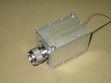 Finished PreAmp using the professional PCBA.
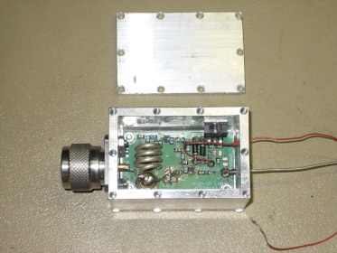 A look inside the beautifully made aluminum box made by Eric, PE1RLF
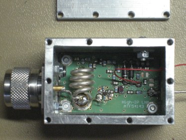 Here you can see the inside with some more detail. The feedthrough capacitor for the supply was not installed yet. The ATC-B capacitors for the series-C as well as the decoupling for L1 also are not according the final build. These capacitors will improve the NF-figure and are mounted during the NF-tests of this PreAmp later this year.
|