HAM History
The HAM radio hobby started at the time I was still living at my parents house in Stadskanaal, if I remember
correct somewhere back in 1980. I was still at high school and was good friends with Be, PA3AOT, who was living as neighbor a block away. He teached me lots of interesting items and I was catched by the thrill of HAM-radio.
 Placing tower
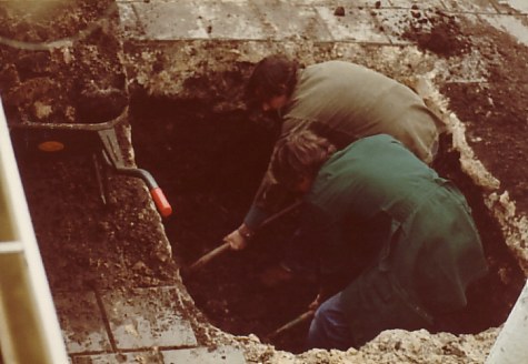
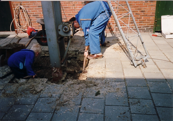
To be able to place a tower, I first needed to convince my parents for the need of it. They agreed but I needed to place it far away from the house. At that time my interest was already mainly VHF/UHF and long cabling to the tower would not give me the optimal results I knew already. Finally I was able to dig a hole for the concrete and the tower could be placed. I bought a 3-piece Versa-tower and Be helped me to make it able to tilt over. The original tower was not able to tilt over, something I needed because of the many experiments with antenna's I planned to carry out.
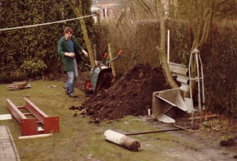 In the picture above and to the left you can see us working on the base of the tower. The tilt-over construction in the left picture (red color) is welded by Be, PA3AOT. The construction is made very solid and it is still in service today (1984 - 2010).
As already said, my main interest was VHF and UHF, also given by the fact that the first exam I did allowed me to work only these bands. My first callsign was PD0MPI, were I did not much QSO's with. Very soon after that I upgraded to C-licence and was active for few years as PE1IYE. This call I used until I reached A-grade licence and the callsign was changed for a third time to what it is today: PA3EXV.
Amateur television was priority
I saw many potential in the HAM-radio hobby and one of them was to be active in Amateur Television also shortened to ATV. Back in the 80's, ATV mainly focused on 70cm AM-modulation. This was the period were the famous designs DC6MR and DJ4LB were used. I personally was never active in tube-amplifier final-stage modulated transmitters, only baseband modulated and class-A amplifiers. I still own the PCBA of DC6MR that I build back then, I don't think it is running anymore. Many components were taken out and re-used in other projects (...).
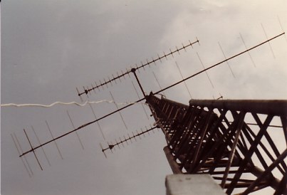
Because of the activity on 432MHz in ATV, there was also the need for good antenna's. I did not have lots of money to spend and I decided to build it myself. I got a design of a 25el. TELO antenna, a design that is no longer known under HAM's today. Because I wanted to do DX with ATV, I decided to do a stack of 2 of these antenna's. In the picture below you can see the result, combined with a well known 16el Tonna or F9FT antenna.
 Time passed by and many time was spend on improving the transmitters and testing them. I remember this period as a very good time, together with a group of other enthusiastic HAM's in and around Emmen (20km away from were I lived) we spend long evenings on ATV.
More gain on 432MHz
It became more clear that antenna's were key in making long distance QSO's. This not only rules for VHF/UHF but for all frequencies. It is a know fact that the HAM-station should focus 3/4 on the antenna, the rest is the electronics inside. As an antenna is to be considered reversible which means not only important for transmitting, but at the same importance for reception, I decided to increase the amount of aluminum in the tower for UHF.
I studied lots of magazines (internet was not invented by then...) and decided to rebuild the tower from 2 times TELO into 4 times 23el. DL6WU. That would give me the gain I was looking for to make more easy QSO on ATV into the province of Friesland were also a lot of HAM's were active on 70cm AM-ATV.
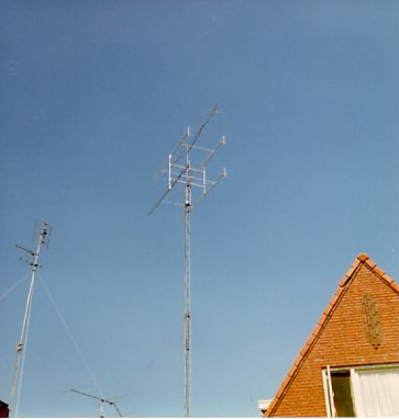
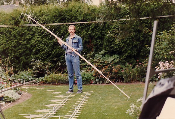 In the picture here you can see me holding one of the four 25el DL6WU antenna's, at that time build with a multiple reflector and folded dipole. On the ground are the other 2 and antenna number 4 is still in the workbench (recognized by the vertical elements at the left hand side of the picture).
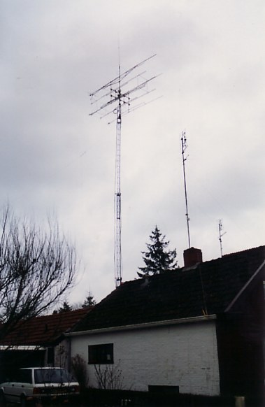
The 4-stack of the 25el yagi's for 432MHz were configured in a boxed configuration. To minimize windload on the rotorpipe, the H-frame for the stack was placed as low as possible, having the 16el. VHF yagi on top of that. The result was a good system that was very well capable of doing nice ATV-QSO's over longer distance. It was in use for several years and gave an impressive view from a distance...
 Because the tower was put relatively close to the house, I needed to be very careful not to risk blowing it over in high winds. Every time high winds were forecast or thunder was expected I lowered the Versa-tower to it's lowest position. As soon as it was save again, I raised it to middle or highest position.
However here have been many HAM's unlucky in the past were there antenna's or even complete towers have been ruined by high winds. I thought I was prepared for this by taking everytime precautions and look forewards to the weather predictions.
Icerain damage
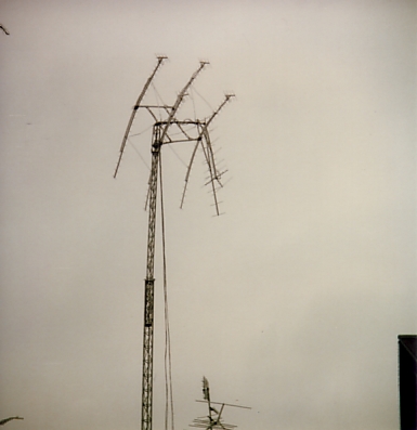
One day, during winter, the northern part of Holland was struck by heavy icerain. It happened suddenly and during nighttime. The Versa-tower was in the highest position because the evening before that good conditions for DX on UHF were present. I did not see any need to lower the tower and the next day we received alarming phonecalls from people living next to us. I did not know what was going on, until I looked outside; The combination icerain and gusts of high winds, made the rotorpipe to bend. I was not able to lower the tower because of this habbit of Versa-towers not to be able to lower in high winds. Large sideway force make too large friction and one is not able to use the winch anymore. Towers like made by the dutch company 'Bijzen' are equipped with rollers and do not have this unwanted friction in high winds.
The only thing for me to do is to sit and wait until the ice was melted and winds were down. After that I could take a closer look on the damage and it became soon clear that I needed to rebuild the complete setup...
  Adding 23cm yagi's
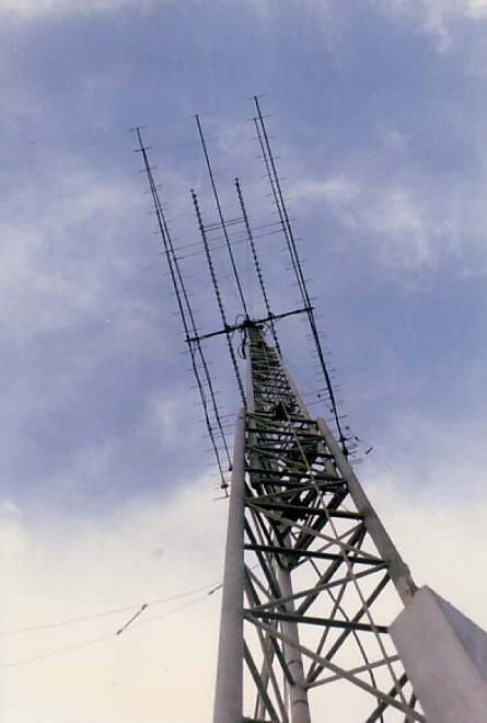
During the rebuild, I decided also to start activity at 23cm. Looking at the nice results I got from the boxed 432Mhz yagi's, I decided to do first time right on 1296MHz as well. I found the detailed drawings of the 65el SHF-design antenna and made 4 of them. This would result in a 23dBd setup for 1296MHz.
Like I did not learn from the damage caused a few months earlier, I decided to mount the 4-stack for 23cm as high as possible abobe the bearing in the tower. In the left picture here below you can see what that looked like...
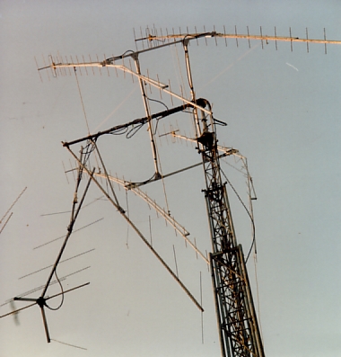
  Of coarse that was not a good decision. The few meters of additional height could not compensate for the many sleepless hours were I was afraid to loose the top-section again. A few moths later the setup was changed to a more stable situation were the 23cm stack was placed inside the stack for 70cm. The 144MHz yagi moved to the top of the rotorpipe again. The situation is showed in the above right picture. It was used in this configuration until the complete tower was disassembled and moved to my house in Schoonebeek, were I meanwhile was moved to.
Here a nive view from the base of the tower, were the VHF beam, the 2 stacks for 70cm and 23cm and a open feed for shortwave are visible.
 Adding support towwer for short wave
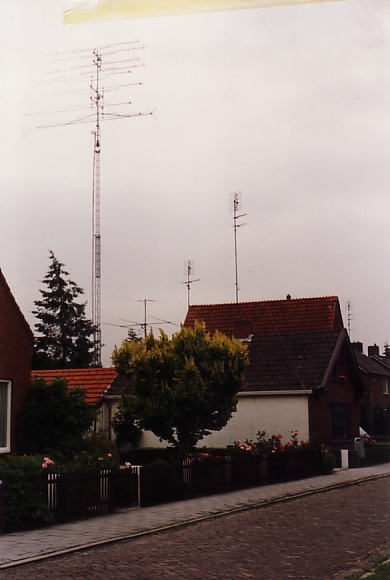
To fill evening hours without lots of activity on ATV or 144MHz, I added a dipole with open feeder to my station. The dipole consisted of 2 legs, each 20 meters in length. Because I did not had a good support to mount the far-end of the dipole in the back garden of my parents' place, I got permit to place an extra tower there.
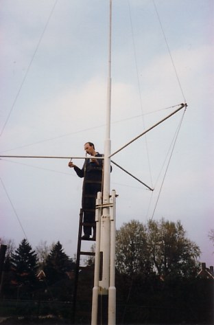
The tower was made from old lightpoles and was also able to tilt-over. It was more a welding experiment for myself... The support tower was made at such a height, that the dipole running from the top of the Versa-tower was horizontal.
80 meter HB9CV experiment
There was another idea why I wanted this height for the support tower: I read an article were someone made a 2 element HB9CV beam for 80mtr band pointing upwards. This I experimented with also. The director was the wire runnin
 g between the top of both towers, the reflector, longer in length, was at 1/8 of a wavelength running in parallel from the lower ends of the to towers. Because of this 1/8 wavelength needed in between the director and the reflector of the HB9CV, this was possible to accomplish with the towers I made. One can ask: on 80 meters and pointing upwards? Why not aim for a low take-off angle to work DX? My intention was to be as loud as possible in the famous Dutch language net, every ebvening for dutch-speaking HAM's. g between the top of both towers, the reflector, longer in length, was at 1/8 of a wavelength running in parallel from the lower ends of the to towers. Because of this 1/8 wavelength needed in between the director and the reflector of the HB9CV, this was possible to accomplish with the towers I made. One can ask: on 80 meters and pointing upwards? Why not aim for a low take-off angle to work DX? My intention was to be as loud as possible in the famous Dutch language net, every ebvening for dutch-speaking HAM's. The experiment did not turn out very good. The problem was the weight of the phasing-line running from the middle of the director to the middle of the reflector. Imagine the wellknown 144MHz version of the HB9CV were a small piece of copper wire makes the needed rotation in phase from director to reflector. That is also needed in this 80meter version. Together with the weight of the feeder-line running to the upper wire, I could simply not apply enough force on the upper wire (director) to make enough ground clearance. The top sections of both towers were under too much stress. Nice experiment though, it is still in my mind to repeat another time but have higher towers to have suppurting ropes to the centre of the HB9CV construction.
In the picture to the right you recognize me painting the support tower.
Moving to new location
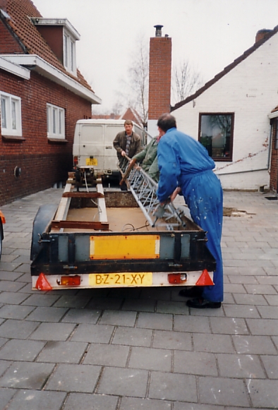
Most of us have a period of big changes in their lifes. Sometimes this is due to facts not being able to influence, sometimes we can. The big change I am talking about is going to move from my parents house to a place were I start to build a place were my YL and me could life together. We moved in 1995 to Schoonebeek and got married late 1996. This has been a period were the radio-hobby was not at first place for 2 years. Lots of things needed to be re-done on the house, taking all of the spare time from both of us.
Luckely my new neighbor was willing to help me moving the Versa-tower. The tilt-over construction in one of the first pictures was at that time simply fixed into the concrete. We needed to cut it by means of a torch now and fixed a 1 square meter, 10mm thick iron plate as new base. This is mounted to a new concrete block now at the new location onto 4 M24 threads. In case the tower must be moved another time, we can simply take it of the concrete and move it.
  From here the story can be picked up in the different chapters of this (hopefully) entertaining webpage.
Thank you for your attention so far.
|