2SA13 Antenna
Background:
After using a 16 element F9FT (Tonna) for long time, I found the need to change to a new antenna. This idea came because the F9FT already was repaired quite some times and I got triggered by the nice values in the G/T table presented by VE7BQH for the 2SA13 antenna.
This 13 element antenna shows the highest gain value on a 4 wavelength boom (8.4 meters long).
Searching the internet brought me to the huge antenna system of KB8RQ, that also consist of these 2SA13 antenna's. Contact was made via e-mail to Gary, and first information on dimensions were exchanged. It turned out not to be as easy as first thought. All dimenions I got from Gary turned out to be in american style. Aluminum material in these dimenasions are not available in europe.
This needed re-calculation of the antenna, also because I had some other ideas on the boom-material. Therefore I used the software program 4NEC2 to change the dimensions to metric system, given the possibillity to order material in the Netherlands.
2SA13 re-design:
Originally the 2SA13 antenna is designed by a swedish HAM SM5BSZ. This radio-amateur has his own company in designing and building antenna's called Svenska Antennaspecialists. The first two letters of this company-name (SA) shows the relation to the 2 meters, 13 elements antenna: 2SA13.
On his website all design considerations can be found. SM5BZC Leif, gives free space dimensions for the elements and shows graphs on gain and impedance over frequency from the 4NEC2 software. Also the input-files to start optimizing are given there.
To re-design the antenna and to be able to use materials of own choise, I spend a couple of days on optimising the antenna. My goal was to achieve the same values as originally described by Leif, but not using a mix of 6mm and 10mm element diameters. My antenna should be bould from 8x6mm element materials, having a round taperred boom and insulated mounting method for the elements. Only the driven element was to be made from 10mm aluminum tubing.
4NEC2 file:
In the below table are the original "real world' free space dimensions of SM5BZC's design of the 2SA13 antenna. As can be seen from this, the element diameters are 6mm and 10mm. This was done to achieve both good return loss as well as good gain, large bandwidth and clean pattern.
Table 1Dimensions of the 2SA13 in free space.
The dimensions in table1 are slightly changed compared to the dimensions found in 4NEC2. The reason for this is explained by Leif, SM5BSZ were I quote here:
From studies of the impedance vs frequency for an antenna with accurately known physical dimensions we know that 6 mm rods should be made about 2.03 mm shorter than the NEC2(mod) lengths while 10/8 mm tubes should be made about 0.08 mm longer. Table 2 shows the real world free space element lengths for the 2SA13.
Remember this when I change my element diamters from 6mm to 8mm. I have only need to add 0.08mm but this is in practice very hard to do. I have simply neglected this correction and only corrected for boom material according the Boom-correction software available from the designer.
Here is the original input.nec file listed that was base for my calculation (no correction for real world free space as explained above):
CE 2SA13
GW 1 19 0.000 -513.09 0.000 0.000 513.09 0. 3.
GW 2 19 0.000 -492.3 240. 0.000 492.3 239. 5.
GW 3 19 0.000 -475.282 340. 0.000 475.282 340. 5.
GW 4 19 0.000 -466.746 761. 0.000 466.746 761. 5.
GW 5 19 0.000 -452.02 1465. 0.000 452.02 1465. 5.
GW 6 19 0.000 -443.218 2262. 0.000 443.218 2262. 5.
GW 7 19 0.000 -442.059 3103. 0.000 442.059 3103. 5.
GW 8 19 0.000 -443.808 3970. 0.000 443.808 3970. 3.
GW 9 19 0.000 -438.747 4858. 0.000 438.747 4858. 3.
GW 10 19 0.000 -435.408 5801. 0.000 435.408 5801. 3.
GW 11 19 0.000 -436.863 6730. 0.000 436.863 6730. 3.
GW 12 19 0.000 -442.482 7563. 0.000 442.482 7563. 3.
GW 13 19 0.000 -444.161 8350. 0.000 444.161 8350. 3.
GS 0 0 0.001000 0.000 0.000 0.000 0.000 0.000 0.000
GE 0 0 0.000 0.000 0.000 0.000 0.000 0.000 0.000
EK 0 0 0 0 0.00000E+00 0.0000 0.0000 0.0000 0.0000 0.0000
LD 5 1 0 0 0.24010E+08 0.0000 0.0000 0.0000 0.0000 0.0000
LD 5 2 0 0 0.24010E+08 0.0000 0.0000 0.0000 0.0000 0.0000
LD 5 3 0 0 0.24010E+08 0.0000 0.0000 0.0000 0.0000 0.0000
LD 5 4 0 0 0.24010E+08 0.0000 0.0000 0.0000 0.0000 0.0000
LD 5 5 0 0 0.24010E+08 0.0000 0.0000 0.0000 0.0000 0.0000
LD 5 6 0 0 0.24010E+08 0.0000 0.0000 0.0000 0.0000 0.0000
LD 5 7 0 0 0.24010E+08 0.0000 0.0000 0.0000 0.0000 0.0000
LD 5 8 0 0 0.24010E+08 0.0000 0.0000 0.0000 0.0000 0.0000
LD 5 9 0 0 0.24010E+08 0.0000 0.0000 0.0000 0.0000 0.0000
LD 5 10 0 0 0.24010E+08 0.0000 0.0000 0.0000 0.0000 0.0000
LD 5 11 0 0 0.24010E+08 0.0000 0.0000 0.0000 0.0000 0.0000
LD 5 12 0 0 0.24010E+08 0.0000 0.0000 0.0000 0.0000 0.0000
LD 5 13 0 0 0.24010E+08 0.0000 0.0000 0.0000 0.0000 0.0000
KH 0 0 0 0 0.15000E+03 0.0000 0.0000 0.0000 0.0000 0.0000
EX 0 2 10 0 0.10000E+01 0.0000 0.0000 0.0000 0.0000 0.0000
RP 4 45 90 0 0.18000E+03 0.0000 0.0000 0.0000 0.0000 0.0000
EN
A four stack of these antenna's produce the below perfomance:
Gain 20.40 dBd
Half Power Beam Width 13o (E and H planes)
F/B 21.4 dB
G/T -1.44 dB horizontal, -1.34 dB vertical.
H-plane and E-plane calculations are resulting in the below plots for a 4-stack of these antenna's:
 Picture 1: E-plane plot for a 4-stack 2SA13 system
 Picture 2: H-plane plot for a 4-stack 2SA13 system
Practical build (PA3EXV):
In this chapter I will give some practical information as well as pictures how I made my first 2SA13 antenna by using materials that are available in the Netherlands.
I have decided to use a round boom, larger diamter in the middle section, slowly decreasing in three steps towards fron and end. This is called 'taperred boom'. The middle section is made from 35x31mm round tubing, towards the rear and front are pieces of round tubing 30x26mm inserted in the 35x31mm, and at last the front and rear section of the boom is made from 25x23mm round aluminium tubing.
In table 2 below, these boom materials have given colors for the same diameters. In this way one can see what element is mounted into what boom material. This is needed to be able to calculate the various corrections on the element length.
table 2: Overview 2SA13 re-design by PA3EXV
Boomcorrection:
The boomcorrections for the elements are calculated by using the tool SM5BSZ made available. This tool is more sophisticated compared to the correction factor DL6WU supplies. SM5BSZ involves not only the boomshape, but also the hole-diameter in case of isolated element mounting is used, distance to nearest boomend and wall-thickness of boom is used in the calculation.
The tool is called BC, a short for BoomCalculation. The tool is available here.
After giving the used materials into this tool, the outcome is table 3 (see below). This information is fed into table 2, resulting in the real element colomn.
table 3: Boom correction calculations
Practical boom-cutting from raw material:
Table 4 in this chapter gives the practical builder the dimensions for cutting boom material from raw lengths of 6 meter. The colomn 'Real length (to cut from material)' is to be used for this. It has already been stretched by an overlength to fit in the next tube section except for the middle boom part.
Section 4 has a bit less overlength to avoid a doubling of wallthickness at element D8.
table 4: Boom materials
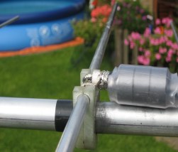
The different boomsections are put together by cutting a 100mm long opening at each larger boomjoint. The smaller boomsection that goes into the next bigger one is to be wrapped in a few layers of PVC sticky tape to fill the 1mm gap. After inserting each boom section into the other, a stainless steel hoseclamp puts pressure on the joint. An additional stainless parker prevents the boomsection to slide into the next bigger section.
After completing the whole boom, one should end up having a total length of about 8400mm (8.4 meters). Keep close eye on the boomsection length in the first colomn in table 4 as this is leading in the inserting length of each tube. If not taken care of this, one might end up in element placing too close to a joint.
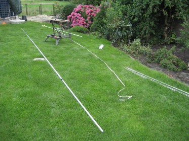 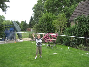 On the two picture above you can see the result of all the above theory. I had the help of a very young radio-amateur (7 years of age) as you can recognise on the left picture...
Element mounting:
The elements are cut from 6 meter length round aluminum tubing 8x6mm. They are cut to the lenght taken from table 2, colomn 'real-element'. As said earlier, the elements are mounted isolated through the round boom. This is by far the best choice taken environmental considerations into account. This is also the cheapest solution, because the used isolators can be ordered for only a few Euro per 50 pieces. Although it would have been better to use PTFE (teflon) isolators, this turned out to be much more work on the lathe. That is why I decided to use simple Nylon isolators and check for changes in permormance after these isolators were exposed sometime to rain. The background for this is that Nylon tends to take vapour in the first period intil the small openings are saturated with water. No negative effects were found, so this is the way to go despite other advices around me. Good luck to machine these isolators yourself if you think it is better to use PTFE. I had the array of KB8RQ in mind, that hold 24 antenna's with 13 elements each. A lot of isolators...
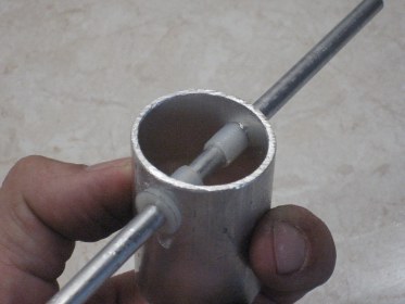 On the picture left is the method shown on a piece left-over material. The isolators are purchased from Farnell, and called M6x12 Nylon spacer.
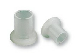 The Nylon spacers are first hammered into a 7.8mm hole in the sidewall of the boom. Indeed this requires a drill of the right diamter. The edges of the spacers are filed to give a smooth edge to be easier mounted into the slightly too small hole. After this the elements can be hammered into the Nylon spacers. The end of the element is filed to a round edge and after being in place, the Nylon spacer gives very good grip to ensure no movement.
Driven element (dipole):
Because of the 50 Ohm design of the 2SA13 antenna there is only a simple construction needed for the driven element. This consists of two pieces 10mm aluminum tubing, seperated in the middle and located at the right location on the boom.
To connect the BalUn to the aluminum dipole, a piece of brass tubing 8x6mm is pressed into the 10x8mm dipole halves. This is causing the aluminum to stretch in diameter a bit and gives good electrical contact. The pieces of brass tubing are 40mm long and are hamered as deep as possible in the dipole halves. When done, they and are cut to leave 5mm exposed to the aluminum tubing were the inner of the BalUn cable is soldered.
Now a piece of good RF isolation material is machined to give mechanical strength to the middle of the dipole. For this material I used 8mm thick epoxy material that is filed to round shape to fit into the 6mm inner of the two brass tubes that rage out from the aluminum dipole halves. This epoxy material gives a stable distance between the dipole halves of 12mm.
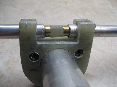 After completing the dipole itself, it was time to construct the dipole holder. Also here the 8mm thick epoxy material is used. It is shaped to fit tightly around the 25mm boom and an opening is left for the soldering of the BalUn.
Ferrite beads or 1:1 BalUn?
Gary, KB8RQ uses two ferrite beads to eliminate RF currents on the outer of the feeder Look on his site how. This is what I have tested also but found these ferrite beads turning warm at 200W RF power. This indicates losses, something that can also explain the lower gain measured at the anual measuring session in Meppel in the Netherlands. I did not purchased exactly the same beads Gary uses, that might also be the reason for this behavior.
Now I use a 1:1 BalUn made from pieces of RG213 coaxial cable. Such a BalUn is made from two pieces cable running in parallel from the N-chassis part were the feeder is connected to. One piece of the RG213 cable is a qaurter electrical wavelength, the other one is 3/4 of electrical wavelength. At the other end, at the dipole, the two inner conductors are soldered to the brass extensions in the dipole, the screens are connected together, but not connected to something else.
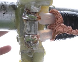  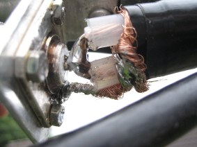 Above are some pictures on how the connections can be made. On the left my first attempt by using the ferrite absorbers I had available. In the middle the N-chassis part in the later setup with the coax 1:1 Balun and on the right the dipole connection. The exposed inner conductors of the RG213 is 10mm long. During the taking of the pictures, the solderings and the dipole holder was not yet covered in epoxy resin. This was done only after some more VSWR testing and adjusting of the dipole and positioning relative to the first director.
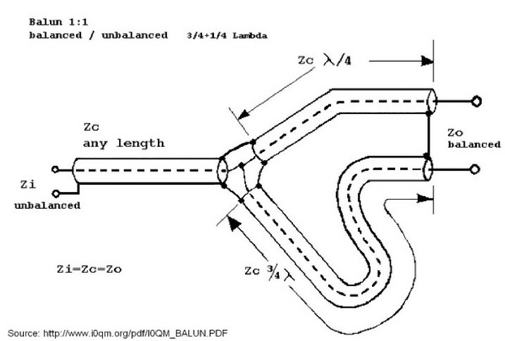
The now used 1:1 coax Balun uses two pieces of 50 Ohm cable, one consists of a 1/4 lambda length, the second piece of coax is 3/4 lambda long.
The below scetch can make things more clear:
 Fine-tuning:
Compared to the values in table 2 (see above), some fine-tuning was needed to get the lowest VSWR in combination to the largest bandwith. Here are the differences written. Keep in mind that not in all cases these changes are needed or changes are needed with slightly other values. My fine-tuning is done by using a Spectrum Analyser with tracking generator connected to a VSWR bridge. With this setup a good overview on all changes is possible.
D1 = 950mm
distance dipole - D1 = 113mm
Reflector not moved
Driven element slowly cut to best best VSWR at 144.3MHz.
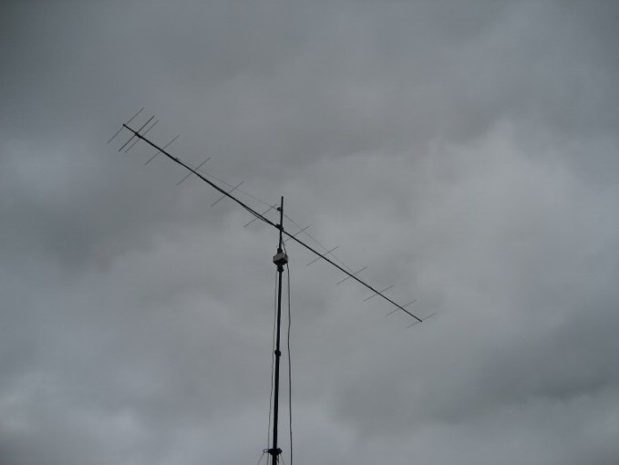
Finally ready!
The final result is the antenna shown in the picture here. This was taken during the anual antenna-measuring event in Meppel in the Netherlands. It was not meantioned earlier, but the 4 wavelength antenna needs some sort of support. In my case I selected a wire-guide over the rop of the boom.
 |